last update: April 25, 2003
 I get a lot of questions per email about a 'regular' tube amplifier. "We don't all have electrostatic loudspeakers, you know!" as if that is my fault! ;-)
But fair enough, it's about time for a simple-to-build, yet good poweramp. I would however not be me if I settled for a standard tube. It's just not my style and besides, for a standard tube there are standard designs.
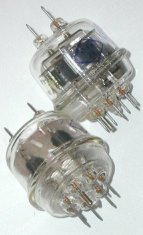
About the time I realised this, my eye fell on an 832 tube that was sitting in my window paine. I bought it (very cheap!) for display, since it has such a cool shape. This 832 tube is a twin beam tetrode designed for RF use. This is one of very few tubes that combine two powertubes in one envelope. All of a sudden I got a vision of a two-tube push-pull poweramp!
I cruised the Internet to find the datasheet. Alas! No datasheet available. The 832A datasheet (in French...) gave only class-C pulse operation data. That's what you get for choosing a weird tube.
 What's a guy to do? I really like the looks of this tube and I think it would make a good amp. From the preliminary data I found on WPS and the Vacuum Tube Gallery it seems each tetrode is in the EL84/6BQ5 ballpark.
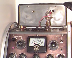
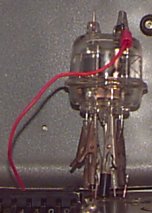
In the end, I decided to write the datasheet myself. I put the tube on my AVO tester (with 7 crocodile clamps, I didn't have a septar socket on hand) and started measuring. The 15W dissipation limit seems about correct. Above that, the tube starts to whistle and if you keep increasing the power, lightning flashes inside the tube will occur. Don't try this at home ;-)
Well, that's not bad at all! The curves are a bit sketchy since the AVO readout is kinda crude. In the curves shown on page 2 of the datasheet a little bit of the typical tetrode kink can be seen, even though this tube is of the beam type. The screen voltage for this measurement was 200 volts, more may decrease the kink but the maximum of 250 volts is very strict. At Va=250V, Vs=200V there is already a little bit of blue glow so I won't go higher. In fact, the curves at Va=200V, Vs=150V are more linear than those at Va=250V, Vs=200V but will impair the power output.
Linearity of this tube is good enough to consider it a feasible candidate for a poweramp. Since the cathode and screen are shared between the tetrodes, there is only one choice: push-pull pentode mode. Ultralinear is out of the question.
Given the -17V grid bias one triode section can be used as driver. Going into positive grid bias didn't look very nice on the AVO. When a double triode is used in long-tailed phase splitter configuration, a 5670 triode might just do the job. Its mu is 35, of which some is lost due to RC loading and the grounding of one grid. A transistor may be used as the current source at the cathode of the 5670, thus requiring no negative power supply.
Now we have a truly simple amp! It suddenly occurred to me that both the 832 and the 5670 are manufactured on both sides of the globe. The 832 is known in Russia as the RY-32 and the 5670 is also known as 2C51. Furthermore, the 5Z4/5V4 and the 6X5 diodes I planned to use in the power supply were made in the USA and CCCP as well! I have both the USA and the CCCP versions of the tubes in stock. So this amp can be used in USA or CCCP mode, or, even better, in mixed mode.
The sound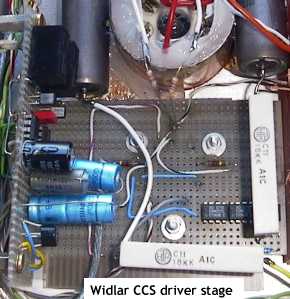 12/24/2001
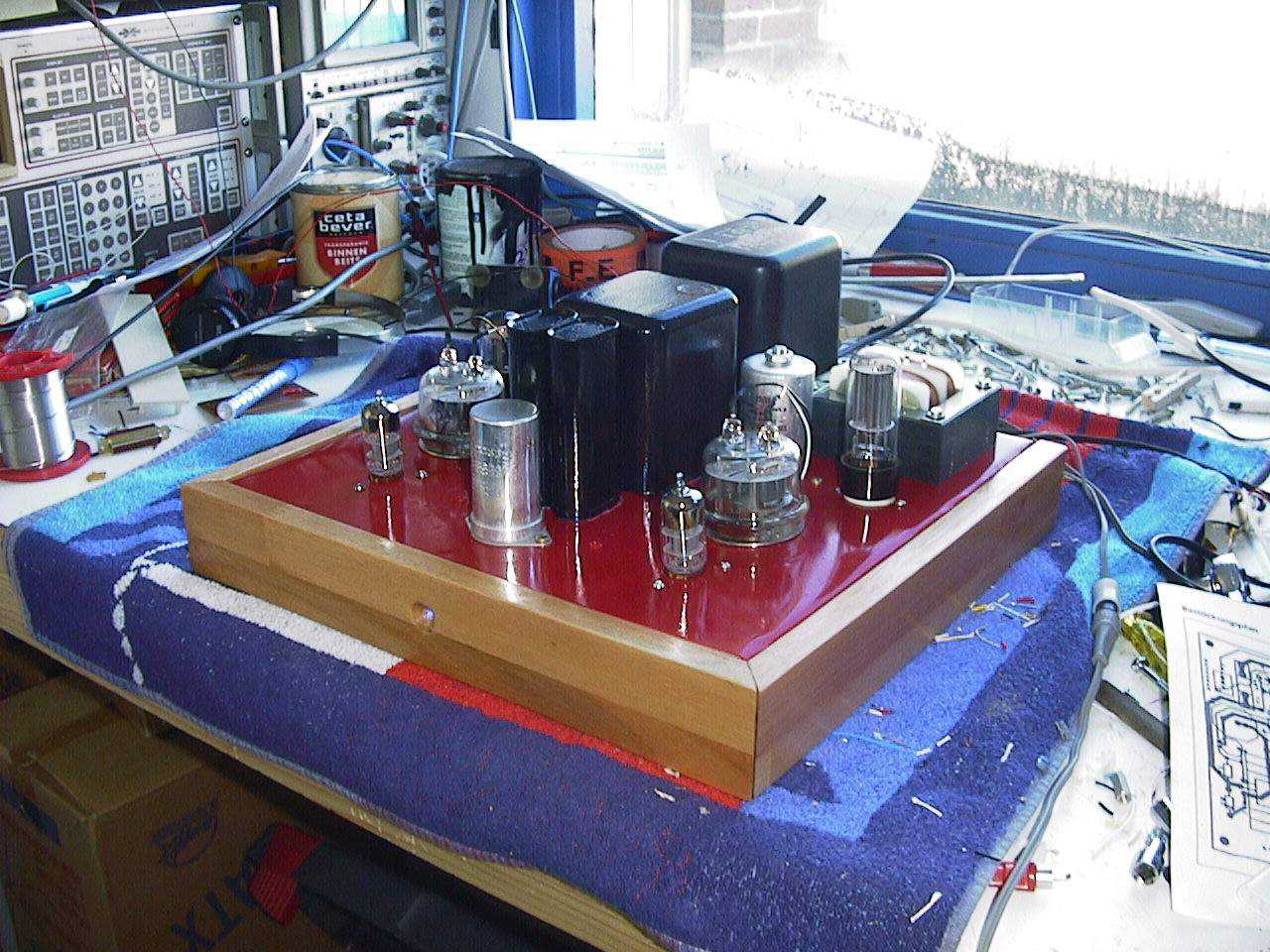
The amp is finished! I altered the driver stage from the NiCd biased longtailed pair to a Widlar CCS longtailed pair. The Widlar current source shows better thermal stability since the equal devices mutually compensate for their increase in temperature. It shows astonishing results: I can leave out the pot one usually puts between the 18k anode resistors for optimal balance. Even without DC balance, due to tubes mismatch for instance, the AC balance is extremely good. The current source shows an output impedance of far greater than 1Mohm. Up to about 5 mA of inbalance (!), I can see no difference in THD on the spectrum analyzer.
Transistor matching of course is an important point in a Widlar setup, hence I used matched transistor arrays, the SSM2210. They come in 8 pin DIL housings which makes them very easy to apply. They will pass about 20 mA each so their not on the edges of their SOAs.
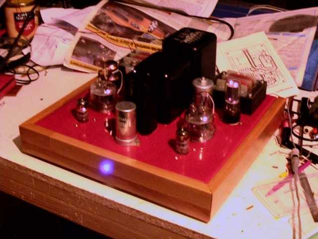
is very good! This amp started up for the first time without hum. How cool is that... I knew we were going to be good buddies from that moment onwards ;-) After about half an hour, it started to sound very good. And that was it: the sound is very stable, this amp does not need to run for hours to warm up! Possibly, it's the driver stage stability that helps. Measured power is about 13 Watts at 1% THD. Good enough. I bet on this 832 tube and it turned out to be absolutely worth its money, this amp will equal your EL84 / 6BQ5 amp without any trouble at a fraction of the cost, and the tube is much niftier ;-)
Page 2: Construction ->
Page 3: Feedback ->
12/23/01: Revised driver stage.
11/19/01: PSU design ready; construction started.
11/06/01: Amplifier signal section design ready.
11/05/01: Made 832 curves and datasheet.