tube output stage for voltage output sigma-delta DACs
last update: Sep 07, 2003
They all share the common idea: high oversampling & noise shaping ]
What are the main differences between sigma-delta DACs and multibit DACs?
Measuring the outputs on a Pioneer LegatoLink DAC I found a peak-to-peak value of 1.75 V for a 0 dB digital sinewave.
The output voltage requirement is about 2V rms (5.6 V peak-to-peak). So, the easiest way is to amplify 1.6 times in a
differential-to-single ended configuration (a long-tailed pair, my favourite). However, that would involve using a coupling
capacitor from the anodes of the tubes to the output and having a not really low output impedance. That would be
troublesome with some amplifiers.
In this summary, the DAC is regarded a black box, since most don't (want to) know what's inside. Doesn't really matter
either, since this stage is set up to be universally applicable to all Sigma-delta DACs.
Then what? Buffering with a cathode follower? Hmm... cathode followers have a questionable reputation.
Mu-stage / SRPP? That improves the output impedance, but involves two more tubes and still you have the coupling cap.
Besides, converting from differential to SE is tricky here.
 Then another option came to mind: use an output transformer! Why not? It converts differential into single ended, acts as
plate load for the tubes and eliminates the necessity for a coupling cap. Additional to that, if I were to use a step-down
transformer, it'd lower the output impedance by the square of the step-down ratio! And if that ain't enough, a transformer
also has a limited high bandwidth, so it contributes to the HF filtering as well! These five (!) functions of one
transformer said 'click' in my head. So I looked around and got the
Sowther 8650 9:1 transformer. Why this one? Well, it had the highest ratio available (low impedance!).
Then another option came to mind: use an output transformer! Why not? It converts differential into single ended, acts as
plate load for the tubes and eliminates the necessity for a coupling cap. Additional to that, if I were to use a step-down
transformer, it'd lower the output impedance by the square of the step-down ratio! And if that ain't enough, a transformer
also has a limited high bandwidth, so it contributes to the HF filtering as well! These five (!) functions of one
transformer said 'click' in my head. So I looked around and got the
Sowther 8650 9:1 transformer. Why this one? Well, it had the highest ratio available (low impedance!).
Having 1 Vrms in, 2 Vrms out and a 9: 1 ratio, you get 18 times needed amplification. Because of the OPT loading of the
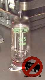
tubes, they will run at almost full mu, so an 5687 (mu=17) or 3A5 (mu=14) will do nicely. The 5844 has double that, for those
who want over 2V rms output and has a common cathode pin, hence it must have been meant for differential stages, so in that
case that is a good one to use!
The 5844 sounds crystal clear and very spatial. The 5687's strong point is the kick ass bass, top is a little muffled. The 3A5
doesn't really stand out in any way, it's very neutral!
- 5844 version (gain = 28) Note: 5844 is equal to 6J6 / ECC91
- 5687 version (gain = 16)
- 3A5 version (gain = 14)
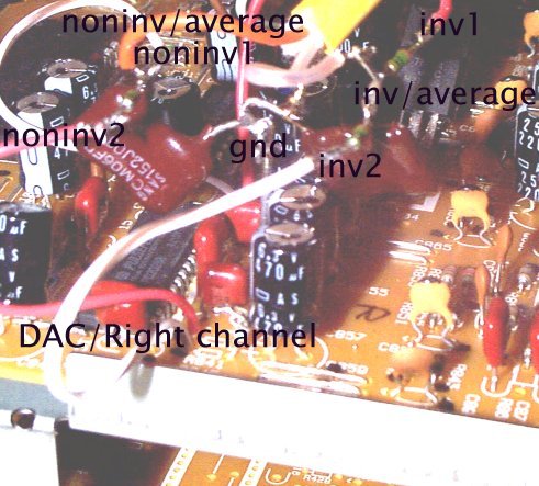
You may find that for every channel, you find two inverted and two non-inverted signals. Then you've got an advanced DAC,
that has dual differential outputs. I have found one such player (Pioneer PD-S801). These dual outputs were meant to be
"averaged" to cancel any errors in the chip. That's why they both are connected to the grids of the 5844 in the schematic.
If you find only one inverting and one non-inverting output, don't worry, just connect only one per channel.
The 1800pF capacitor, together with the grid-resistor, provides first-order filtering at 100kHz. The transformer adds 1 order of filtering at 120kHz. Together they form a 2nd order filter which is enough for the sigma-delta chip, so the signal path is capacitor-free!
Both the inverted and non-inverted signals are amplified and put through the transformer. Connect one of the secondary leads to ground to avoid hum.
The tubes have a simple, tube rectified PSU. The tubes pull 4*8.5 = 34 mA from the AZ1 which can deliver 60mA. I heard no
hum whatsoever even with AC on the heaters, which is understandable since it's a PP amplifying stage that by nature
has a very high PSRR for common-mode signals. For the 3A5, I've implemented a regulated DC filament supply since it's a DHT.
And this pudding is goooooood.... I wasn't sure about this, it was my last hope for the sigma-delta DAC and luckily it turned out OK. The character of the DAC is maintained (and I do like the LegatoLink DAC a lot!) but with much more detail, spatial coherence, and warmth! Warmth! From a sigma-delta DAC and a PP circuit??? Yes! This maintains the level of my former PCM63/SM5842 DAC throughout most CDs, but with some recordings, it just leaps ahead by a mile.
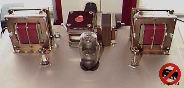
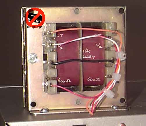
The 5844 circuit sounded like good stuff, so I decided to build a no-compromise circuit. The 3A5 DHT was chosen for this task
because it has the same socket as the 5844 and has nice curves. The Sowter tranny has been replaced by a custom-built
amorphous core OPT by Automatic Electronic from
Schagen, the Netherlands. After a *lot* of fiddling it turned out this tranny
wants its secondary floating (it lost bass and distorted highs otherwise, probably due to capacative effects).
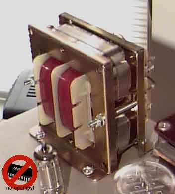 Check out this monster OPT!
A smoothness I only thought possible from the best vinyl!!! Makes one drink whisky in the middle of summer. Boy oh boy:
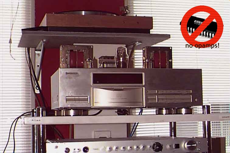
This is my reference player...
After the break-in and evaluation period, I've now built the definitive circuit in- and onto
the top plate of the original cd player. The circuit is activated by a relay connected to the standby switch of the
player (remote on/off control! My favorite gimmick).
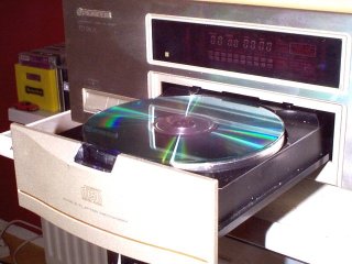
If you've got a good player lying around with sigma/delta DAC, try this! You'll love it! My special recommendation is the
Pioneer Stable Platter type. This is a rigid, TEAC-VRDS-level transport that with a few mods gets even better! And the
LegatoLink is just one of the best sigma/delta DACs out there (it is rumoured to be 'stolen' from Wadia...).
Not a lot! The chassis is already stabilized quite nicely right out of the box. Also, the servos and signal sections are
fed by separate transformers and re-stabilized and buffered right before the DACs. I only added lead bitumes to the
platter. It's a VERY stable Platter mechanism now!
Oh yeah, I added a blue led to the plateau... very kinky... ;)
Digital output:
Attached cascaded inverters to the DOUT signal (on the mainboard) to buffer the S/PDIF signal that's readily available on the
mainboard. Used a 680 ohm series resistor to obtain a swing of approx 1V on the output. Used a BNC connector instead of
cinch for the digital output (nicer).
Comments? Questionz? Remarkz? Let me know, or check the Q&A list below.
-
Q: I don't have a scope. How do I find the outputs on my LegatoLink DAC?
A: Buy a scope! Seriously, I can give you the pinouts, but if you don't have a scope, you're selling yourself short. You can't hope to get good results from any sort of DIY without a proper 2 channel 10 Meg+ scope. -
Q: Does this stage work with the 6SN7?
A: Yes, the 6SN7 seems a very suitable candidate, but needs a higher plate voltage. You can subsitute the 6SN7 into the CDenhancerII circuit for the 5687. The gain will be about 20. -
Q: Are you planning anymore circuits for different tube types?
A: Yes, as I find good results with tube types, I'll put the appropriate schematics online. Only the schematics of circuits that have actually been tested are put online. Right now I'm contemplating the 5676 (dht). -
Q: Why not use a separate DAC?
A: 1/ The LegatoLink DAC rules! 2/ It creates huge problems with biphase (S/PDIF) encoding, ground and HF layouting, jitter, shielding, power supplies, connectors, cablelengths and such. I've had separate DACs but they all were unsatisfying. Bypassing the entire interfacing problems proved to be the answer. Keep It Simple Sweethearts! -
Q: What are the critical components of this circuit?
A: Good question!
The tubes seem to really reveal their character in this circuit. The 5687 sounds more raw, fat on the bottom end, but the 5844 sounds really sweet and open in the mid and high region. 3A5 is one of the smallest DHTs I have come across, but just like its bigger brothers, it has that typical fluancy you just don't get from IHTs!
With respect to trannies: The Sowter is a nice, little, relatively cheap transformer. In the current application, it's very near the maximum specs though. It's probably the best value for money. The Automatic Electronic transformer is something completely different. This tranny is twice as expensive but delivers the goods! On the test bench, I've swung over 2W through it without any distortion. More is probably possible, but who cares. In other words: this is a very overdimensioned tranny. I like it a lot. It took a week of non-stop CD playing to fully burn it in, the highs became much more clear during that time. The mids and lows were OK from the first tone - very organic.
Cabling: Make the signal path as short as possible. Luckily this is very possible with the simple circuit. I use teflon isolated coaxial silver (from old transmitting equipment) that sounds really nice and open. Copper seems more dull.
The cathode resistor is best shared between the channels, to ensure automatic perfect matching. Since it's a PP stage there is no AC on the cathode, so that is allowed. -
Q: Can this circuit be used on DVD or SACD players?
A: YES! As long as they have 1 bit converters. In fact, it's very suited for SACD since that is a native 1 bit format. I haven't tried it myself but give me a player and I'll tubify it... the most analog digital sound ever! ;) -
Q: Is it possible to add a digital input to the pioneer cd players?
A: From what I learned fiddling with the player, it might be possible, but I haven't really tried yet. At the moment I have only one digital source, hence the need is not so high. Also, S/PDIF has some very real limitations. If I get around to it, this is the place where you'll read the results first! -
Q: Can't you just use a simple 1:1 transformer and leave the tubes out?
A: In my opinion, you can't. I tried it and didn't like it. Einstein said: "Things should be as simple as possible, but no simpler." This is IMHO too simple. That's why I implented the gain and the stepdown. For every N factor of gain you put in, the output impedance goes down by N squared. You see that you don't need a lot of gain to reduce the impedance to acceptable levels. Ballpark value is 100 - 600 ohms, even though you wouldn't suspect that from your 47k nominal loading. I have a 100k Zin preamp, but the lower output impedance definitely helps in the highs and spatialness. Besides, it doesn't really complicate the design, the tube fits in nicely, can use the primaries as chokeload, and runs at full my at a relatively low B+ voltage.