tube output stage for current output multibit DACs
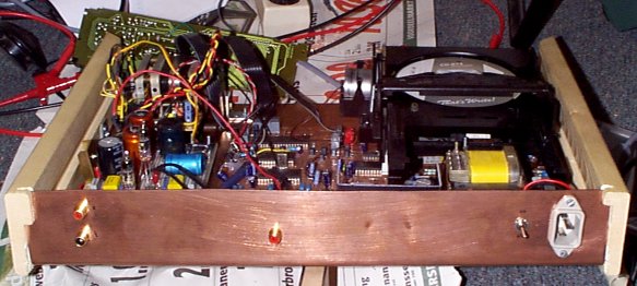
When you take them out of their flimsy plastic housing and put them in sumzing good (like the copper/wood housing above) you have a hell of a transport. Do add an XO low-jitter clock, though.
More info on adding digital outputs and XO clock the bottom of this page...
Maybe in those days the cost-cutting people weren't allowed the random access to stripping good components they are now. Especially the transports of
those days, for instance the CDM-4 by Philips, is great. Nicely suspended on a bed of springs, tangential readout, it's a cutie.
But of course the sound bites wind. If you take a peek inside, you notice a lot of the early-days opamps like the LM833. Rotten. So my idea was
to replace them with good ones. Worked. Improved somewhat, but not enough. However, I did notice a 'talent' in the two players I modded in this
fashion. This had potential.
Then, when I got my third Philips for modification, I wanted to go a little further. Instead of replacing the opamp behind the DAC with a
better one and using a tube stage for the final amplification, I decided to try and skip the opamp entirely.
What is the job of this opamp? It's I-V conversion. The DAC has a current-type output.
Fig.1: classical I-V conversion and filtering method
Why is it done this way?
- The voltage at the output of the DAC is virtually 0. This is advantageous because now the internal DAC switches have only little charge to transfer. In this fashion, it is more likely that all binary weights have a high enough switching speed and thus spikes are avoided.
- The filtering is quite easy, only a small capacitor and resistor will do.
- An opamp is just one, cheap component.
- While it is fast enough for 20kHz sine waves, the opamp feedback loop is not fast enough to linearly process step shaped signals. Since the output of the DAC is step shaped (the size of the step varies from 1 LSB to 2 MSB !!) the error of the opamp is both frequency and amplitude dependant. The results are dynamic compression and loss of spatial information.
- The many transistor stages in the opamp complicate the signal path extensively and unnecessarily.
- The output stage does not glow in the dark.
After making the above observations, I thought:
![]() and got to work.
and got to work.
There are 2 well-known alternative methods for I-V conversion:
- A resistor
- A transformer
The transformer (for instance the Sowther) seems a viable option, but needs a resistor in parallel to have some voltage to transform and thus has the same drawback as the resistor. Also, I don't have one lying around :)
Another I-V method completely is to first buffer the output current of the DAC and only then convert it into voltage. Using this method, the zero output voltage condition can be met while still the conversion is very simple. I chose to go with a common-grid I-V converter:
Fig.2: common grid I-V conversion
As can be seen from fig.2, the voltage on the Idac line is equal to the bias current of the 6021 imposed by the current source on top of
it times the 100 ohms resistor. Using these values, a bias voltage of 1V is ensured. Now the Idac line is at a voltage of 1V above agnd. By
means of the 1V voltage source between agnd and dgnd, the Idac line is now at dgnd, and thus it is at zero volts as far as the DAC is
concerned.
The DAC output is 4 mA. Some of the current is dumped into the 100 ohms resistor and some is transferred to the anode of the 6021. There it is
converted into voltage by the Rp. Some fiddling and tweaking gives you the right voltage you need, I chose for 2V rms here.
After this stage follows the passive filter stage:
Fig.3: filter and buffer stage
The filtering is 1st order passive RC. The 6021 is in cathode-follower configuration, so the output voltage is 2V rms (DIN). The 470uH together with the 1.8nF form a notch at 4fs. Because this notch is in place 1st order filtering is enough to supress the HF noise, since the TDA1541 is a 16 bit x 4fs device.
We now have a simple I-V converter and a simple filter with low output impedance.
The sonic result is astounding. The signal dynamics are very good due to the current source on the first 6021 and the passive I-V conversion.
From the very much improved spatial resolution can be deducted that the absence of the opamp and the simple filtering affect phase much less
than before.
This is a very simple output stage that can be adapted to suit other DAC ICs, such as the Burr-Brown PCM63, PCM1704 and other multibit DACs.
It has made me wonder whether this configuration can also be adapted to suit 1-bit DACs. This design, which is still under construction, will
be CD enhancer II.
This makes it better! :-)
Attach two cascaded inverters to the DOBM (pin 14 on the SAA7220) to buffer the S/PDIF signal that's readily available on this pin. Use a voltage divider to obtain a swing of approx 1V on the output.
Low-jitter clock:
Cut away the 12 MHz crystal. Get an XO low-jitter 12 MHz crystal, use a clean power supply for this one. Connect the output of the XO crystal
to pin 11 of the SAA7220.
Comments? Questionz? Remarkz? Let me know!