Deprecated: Array and string offset access syntax with curly braces is deprecated in /profiles/i/it/its/itsonlyaudio/itsonlyaudio.com/wp-content/plugins/easy-table/inc/Encoding.php on line 156
Deprecated: Array and string offset access syntax with curly braces is deprecated in /profiles/i/it/its/itsonlyaudio/itsonlyaudio.com/wp-content/plugins/easy-table/inc/Encoding.php on line 158
Deprecated: Array and string offset access syntax with curly braces is deprecated in /profiles/i/it/its/itsonlyaudio/itsonlyaudio.com/wp-content/plugins/easy-table/inc/Encoding.php on line 159
Deprecated: Array and string offset access syntax with curly braces is deprecated in /profiles/i/it/its/itsonlyaudio/itsonlyaudio.com/wp-content/plugins/easy-table/inc/Encoding.php on line 160
I’ve been looking at designing a D/A converter for a while now. In my experience these are some of the hardest audio components to do right. It started with building output stages over a decade ago and at some point I even found myself in a company designing a D/A converter transistor by transistor.
However, as recent experiments have shown, I still have a lot to learn.
The reason why a D/A converter is so hard is because you have no possibility for feedback, since you’re translating into a new domain. You literally have to synthesize an output signal out of nothing according to the digital numbers handed to you.
Lots of listening tests have shown that if the output stage is good enough, you can always hear the sonic signature of a particular D/A chip, be it the architecture (switched-capacitor, steered current, R2r, etc) or even noise shaping loop structures. Oddly though, they all measure pretty much perfect. That’s an annoying discrepancy as it leaves you half blind whilst designing!
I wanted to see if I can see some of that subjective impression in measurements. As it happens I had two and a half D/A converters available.
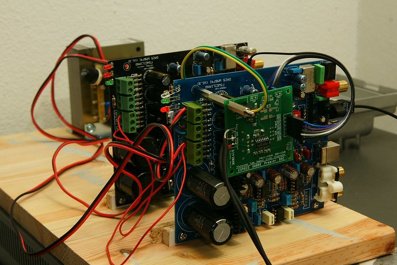
First there is an eBay WeiLiang WM8741 D/A converter which I bought as a kit to see how the WM8741 performs in a cheap setup. The whole thing costs about $55 shipped which is mind blowing as the chip itself costs around $10 and you get some first grade opamps, a PCB, and all the components. The output stage in this one (v1.3) was designed exactly according to the wm8741 datasheet. But there were some pretty grave design errors on the PCB – the voltage regulators were different in the layout than on the schematic (yes, I did fix them).
But after complaining about these errors I was given a new board which has version v1.9. Power supply is better (i.e. not broken) and the WM8741 can now be switched into high or low rate (pin 22). But suddenly I noticed the entire analogue stage had changed, so I decided to hook both output stages to one D/A converter and measure the differences. A comparison between these output stages is in the pipeline.
Lastly, I could not resist a dirt cheap ESS9023 I2S board from diyinhk. Tapping the I2S signals from the WeiLiang board, I now had two and a half D/A converter to play with.
The WM8741 with v1.3 output stage and the ESS9023 have exactly the same output voltage (2.0 Vrms for 0 dBFS). So in this post we’ll focus on these two.
First, let’s do the standard measurements. The things you can basically read from the data sheets.
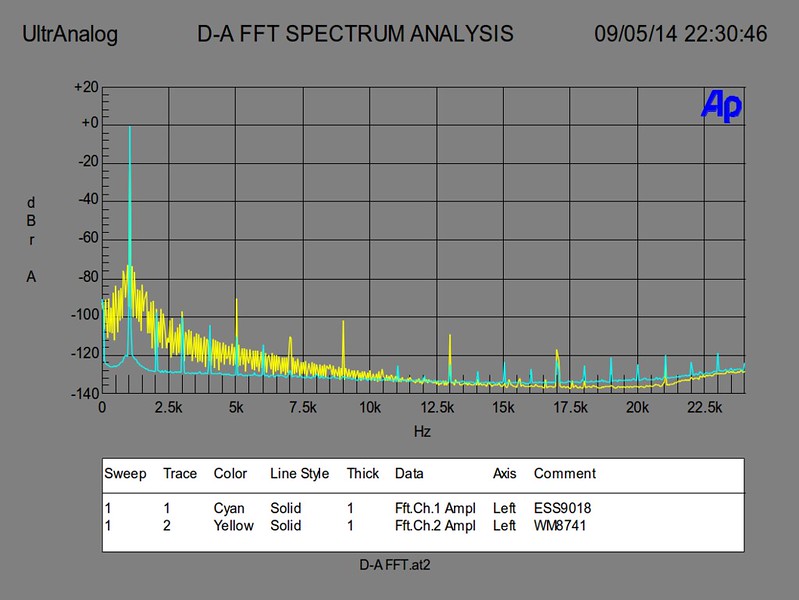
Harmonic distortion
!!! – I made a huge mistake and labeled all measurements ESS9018 instead of ESS9023. Please be assured it IS the ESS9023 all the time.
There is an immediate problem here. The wolfson 8741 output is not exactly clean, whereas the ESS9023 is pretty exemplary. Something is modulating the signal and the prime candidate is the power supply.
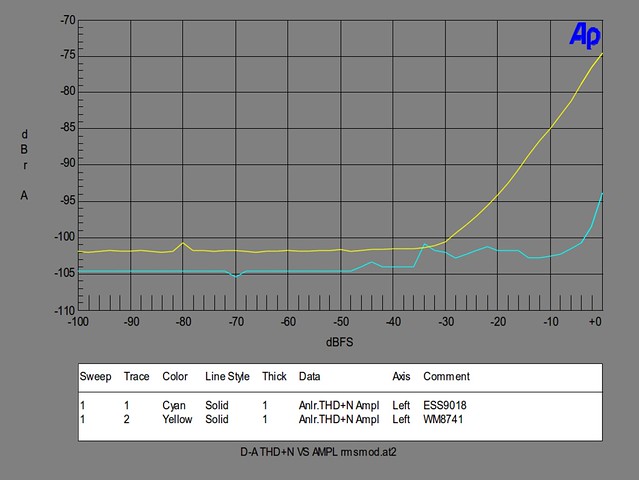
The THD+N reading on the AP System Two considers not only the harmonics, so we may assume the blame in the 50 Hz components for the reading on the wm8741. It is performing worse in the WeiLiang board.
Power supply rejection ratio
From the previous graph it is clear we need to look at PSRR, since the WeiLiang boards are showing a fair amount of supply disturbance.
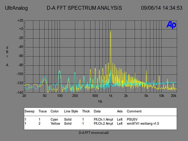
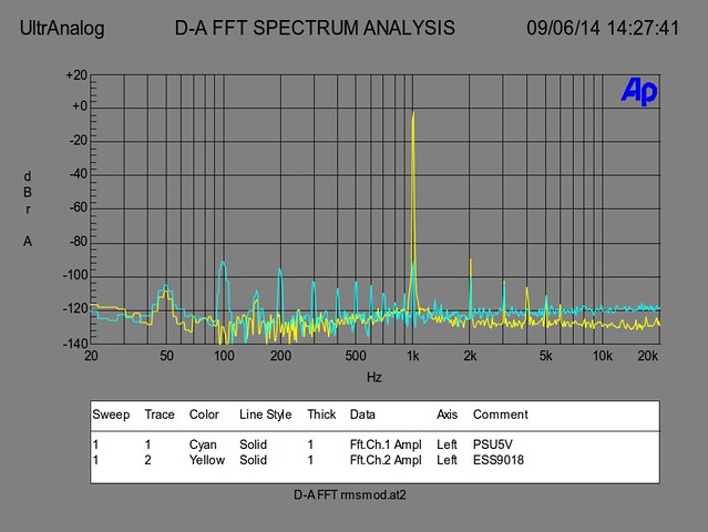
So, we’ll probe one channel on the D/A converter output and the 5V supply rail and look at the respective spectra. First up, the WeiLiang wm8741.
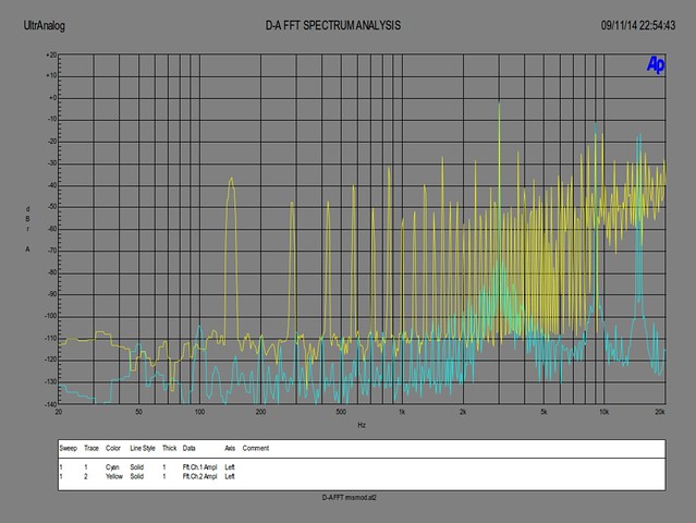
There’s your problem. In the 20-400 Hz you can see the DAC follows the power supply exactly: it has 0 dB PSRR. When we get closer to the 1kHz signal region, the signal starts to modulate with the power supply components.
This is because the wm8741 is a charge distributing D/A converter. It first samples reference voltages onto a signal weighted number of capacitors and then onto the output. So, any disturbance on those reference lines is directly modulated onto the output. It looks worse than it is, given that the maximum component reaches only -75 dB, but this is definitely something that can and should be improved on the WeiLiang design.
Now, let’s to the same with the ESS9023.
Here we see a very different picture. The ESS9023, fed from exactly the same rail that feeds the wm8741, seems to almost completely reject the 50 Hz components. They don’t show up in the 50-1kHz range at all, and also don’t modulate with the 1 kHz signal. Very good news for ESS.
Frequency response
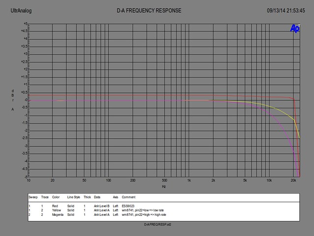
Another problem: the frequency response of the ESS9023 is pretty much ideal again, but the wm8741 is already down 3 dB by 20 kHz.
Part of this is the WM datasheet output stage, which we’ll discuss in a later blog post, another part is the 8741 sample rate. The WeiLiang v1.9 board lets you set pin 22 on the wm8741 high or low (disabling high-Z which is medium rate). Since the AP2322 can not go higher than 48 kHz, we’ll set the rate to low which makes the frequency response better. Still: advantage ESS.
Linearity
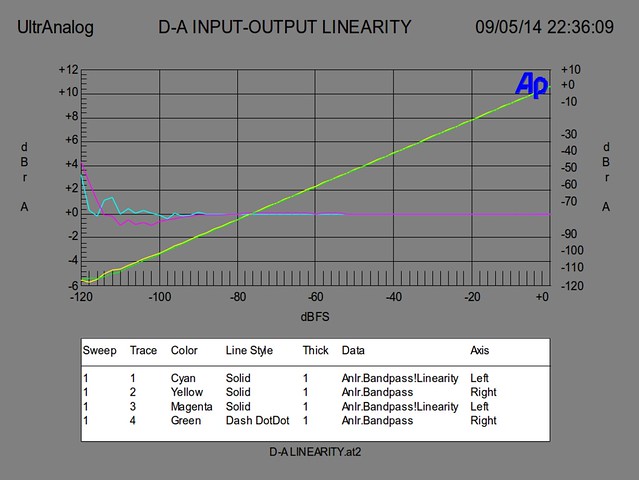
Not much to see here. Both are exemplary.
Listening tests
Now it would seem that the ESS9023 is in the lead against the WeiLiang board. A WM8741 chip can perform much better than this, but in order to do so it is clear that the power supply and the output stage will need serious work. And the ESS9023 has both of those integrated with no need for external components.
This is where the story would end, if we didn’t have ears or if we had learnt that good measurements guarantee good sound. Since that’s not the case, I hooked up the wm8741 WeiLiang v1.3 and the ESS9023 for an A-B comparison. Here are my notes.
| wm8741 | ess9023 |
|---|---|
| hum is audible with ear to the loudspeakers but not during normal listening | Very well rounded. Very friendly. |
| Top end is really clean. Voices are very understandable | Can't match 8741 for holographic sound stage |
| Needs an hour to break loose | dynamics may be better than wm |
| Midrange annoying when cold | Very close to the character of the AKM D/A in my delta 1010. A bit better |
| Raspiness in voices is realistic. Voice pinpointing is GREAT | Diffuse voices w.r.t. WM |
| Not overly impressed with dynamics | integrates well with sub channel (on AKM D/A channel) |
| Sound staging is just awesome | Sound stage is FLAT |
| Sound staging can get TOO full and sound cramped or sharp | I'm bored |
| Just understood lyrics of a song I'd heard a thousand times for the first time | high freqs sound muffled/shushed. How can that be??? |
| Little voice reverbs are impressive | Little voice reverbs are audible |
| You first notice things you've never heard before on the WM | Rhythm& pace/timing better than WM |
Wow. That’s just confusing. The ESS had passed every test with flying colours but when listening to it, I found myself bored or distracted – anything but captured by it. The wm8741 was a bit of a diva: a bit of a morning temper and when finally warmed up really good on good material, and really bad on bad material. But over the course of the next two days, I couldn’t bring myself to disconnect the wm8741 because it was addicting, even knowing it was very flawed and could be so much better. When I finally broke loose of its grip and got the D/A converters back on the Audio Precision, I thought of one more test to run: the TIM test.
Now this needs some clarification as it is not as well-known as it should be. Whom better to quote than Bob Metzler in the Audio Measurement Handbook [pp. 41-42]:
Many audio workers have felt that some audible distortion mechanisms were triggered by changing program material, but not evident with steady-state stimulus such as a single sine wave. […] The most popular technique was proposed by Schrock and Otala. The signal […] consists of a band-limited square wave (typically around 3 kHz) plus a high frequency sine wave “probe tone” of one-fourth the peak-to-peak amplitude of the square wave. The rise and fall sections of the square wave stress any portions of the circuit which have slew rate limitations, and intermodulation products of the
sine wave with the fundamental and various harmonics of the square wave will indicate problems.
This is the reason why I wanted an Audio Precision with IMD plug-in so badly: I wanted to do this test. Let’s look at the result.
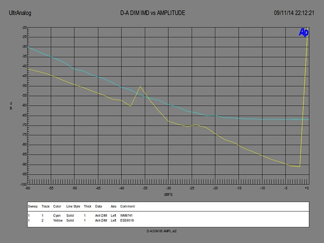
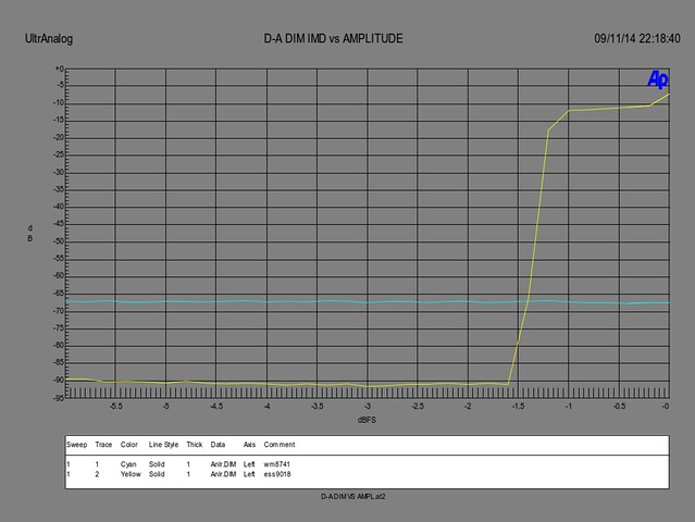
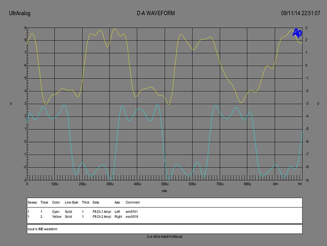
What do we have here? Although the IMD for the ESS9023 is mostly lower than that of the wm8741, there are two very weird kinks in the sweep (and I’ve re-run this with hundreds of measurements, it’s not a measurement glitch). I normally don’t like kinks in sweeps – I would prefer higher values of distortion as long as the sweep is smooth. The kink at -37 dBFS is therefore odd but not as concerning as what happens near 0 dBFS – it shoots up!
A level of -10 dB of intermodulation cannot be for real, right?
As it turns out, it can.
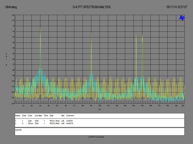
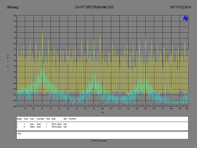
The IMD pictures show that at high amplitudes, the ESS9023 is modulating just about anything with everything. The reason for this could be anything, but my money is on internal biasing inside the chip that cannot follow the fast shifts in operating points. Either cascodes run out of current, some common-mode loop cannot keep up with the differential loop, or what have you. The time domain plot shows that at every slope of the square wave the circuit is upset and starts to drift about, even though the smaller sine waves are still being reproduced.
Interestingly, this leads more weight to the case for digital volume control, as the distortion is only so pronounced at the very top of the digital range. However that is with just three sine waves, the lowest of which is 3 kHz. Music is a bit more complicated than that so the problem may well be far worse for actual audio signals.
It should not be possible for the signal to influence the operating point so gravely – that’s where the ‘small signal linearity’ axiom is built upon. It is just this that vacuum tube circuit excels at (and why I started building those). Running at several hundred volts, a few volts of signal would not upset any part of the circuit, which explains why they’ve survived in special applications (microphones and high end) up until this day.
It seems very contradictory that the ESS9023, which performs flawlessly on sine waves, falls over with a test signal like this. I’m afraid it is perfectly understandable that if an engineer is asked to design to specifications such as THD, SNR and cost, those are the only places that will receive attention and optimisation, often with some very clever tricks to shine under those measurement conditions. Some times at the cost of the aspects that have not been specified or will not be checked. Almost never on intent though.
And it’s not just ESS – I’ve already measured other D/A converters from other brands that show the same behaviour. And you don’t need an Audio Precision to notice when something goes so bad. Just take the IMD test signal and look at the waveform or the spectrum.
The lesson should not be to design only by ear – that leads absolutely nowhere. But neither should one design audio circuitry just to put nice numbers on a data sheet. Maybe there is a middle way?
Many thanks for your post, because of it I was able to diagnose and fix my own WM8741 DAC design which exhibited fairly high distortion (-70dB highest harmonic, and great many of them). I tried everything for several weeks, configuring every register in ASRC receiver before it and the DAC itself and was about to give up, when I found your site and your measurements. Your FFT graph looked quite similar in shape, if not absolute amounts, to mine (spikes everywhere). Long story short, my fancy voltage regulator (ADM7150) was actually not doing much load regulation at all, thanks to a bad choice of decoupling caps on my behalf. It wasn’t obvious on oscilloscope when watching the rail as there was no oscillation, it simply didn’t do much rejection of load on low frequencies. But you’d only get to see it if you fed it a sine and watched FFT. Thanks again!
Hey Andrija, that’s great to hear – both that this post was helpful and that you found a good solution!
Thanks for reporting back. I’m going to look into the ADM7150 for my board. Would you care to share the circuit you came up with?
For the regulator? That’s just a few caps and resistors like in datasheet – but I added far more capacitance with low ESR, which it didn’t like. After some discussion on diyaudio which apparently included someone from Analog who worked on the evaluation board, the take out is to simply use a 10 to 30uF ceramic capacitor at the regulator output. Also, follow the PCB layout they outlined. That’s it.
Great – I’ll try that! Thanks again.
Excellent post! Would you share a bit more info about the problem with the voltage regulators on WeiLiang boards you’ve encountered?
Hi Petar. Good question, thanks.
There is no real ‘issue’ as such, as they actually work just fine. The thing is, they’re just not good enough. The residual hum (which sits at -80 dB) modulates with the audio as the voltage references are sampled to produce the audio output and hence, these references are as good as the audio is going to get.
Now, modulation is never a good thing and although the boards sound great, we can do a lot better by improving the references and thus cleaning up the signals sampled from them. Andrija suggested the ADM7150 which I have yet to try, another possibility is a huge RC using a Maxwell ultra-capacitor which is what I was thinking about. Unfortunately, a new job and house move has meant I have had no time and no place to try this yet – but I will!
Hang on, I think you meant the problem on the v1.3 boards, right? On one of the LM317s, the ‘OUT’ and ‘ADJ’ pins were shorted together, if memory serves. For some lucky reason, the right voltage came out, but there was zero regulation and lots of hum on the output. I opened the traces and put a resistor between them to restore the right function.
Later boards seem to have the correct application for the LM317s.
For 2+ years I’m using Yuxuan 2 a WM8741 based ASCR DAC board (CS8421 covertor). After few modifications it actually sounds very good.
From your measurements it seems 5V analog is polluted with 50Hz and harmonics, insufficiently suppressed by regulator. Perhaps it can be mitigated in first place by reducing the ripple at regulator’s input? I was bit sceptical about merely 6600uF filter capacitors in digital supply section of my board with almost 300mA consumption. So I added CRCRC in front of it with total of 30000uF.
Examining the board I found something peculiar about the local oscillator (Raltron). It is 5V model and it feeds MCLK of the DAC chip through a resistor of 100ohm!? But MCLK is 3.3V input!? So far no problem. I wonder is this just an overlook of the designer or some trick to make clk slope more steep and reduce jitter?
Sure, adding suppression prior to the regulator helps. Still, I’dd add it afterwards. So much capacitance loads the diode bridge quite heavily leading to 50 Hz inductive spikes all over the board which is also a pain, especially as the board is not exactly a wonder of EMC layout.
Given that a regulator gives you more bang for your buck you could also cascade a few times, if you could suffer the dropout voltage. But- for the money of all those caps I’d probably prefer to buy a better regulator. Each to their own.
Compared to the (much newer) ESS chip, it is a weak spot in the design and it would have been great if the WM8741 could generate its own reference voltages.
Looking at the DAC5 schematics, I see a 3.3V supply for the XO. I do vaguely recall some silkscreen reading 5V but I fitted a 3.3V regulator by looking at the schematic. It works fine here feeding into the WM8805 S/PDIF transceiver which has an excellent PLL generating synchronous SCK for the WM8741.
Jitter really does not come into play when you use the WM8805 as it completely regenerates the clock with an elastic buffer and sub 1Hz PLL bandwidth after catching. There is a very good paper on its performance: “A High Performance S/PDIF Transceiver—Paul Lesso, Wolfson Microelectronics” (which I presented in San Francisco in 2006 since the author was unable to make it). You can buy it from the AES, or it should be available on the web with some googling.
I have very little experience blindly feeding an MCLK into a chip other than some raspberry pi experiments so can’t say much about that. My personal stash tube of WM8805s hasn’t run out yet…
@remco thanks for answering. I’m not aware of the analog design of WM8741, I wonder is the analog output affected more by disturbance in 5V nodes (AVdd/AVddL/AVddR) or midpoint nodes (VmidL/VmidR) are more sensitive. Are the midpoint voltage pins on your Weiliang boards properly decoupled? Sorry to bother with so many questions.
Petar, I’m always happy to answer questions.
AVVDL-AGNDL and AVDDR-AGNDR are the reference voltages the DAC samples and therefore the most critical. This is an open-loop operation.
AVDD feeds opamps and other analog circuitry which has reasonable PSRR and is therefore less critical.
VMIDL and VMIDR are outputs and serve as virtual grounds for opamp circuits. They have 10uF + 100nF each on the DAC5 board.
What would maybe work quite nicely is a constant current source feeding a shunt regulator on this pin, as the DAC should consume a constant current save for some spikes. A cap should absorb the HF spikes and the shunt eats the last bit of variation. Ah, if only there were more hours in a day…
Thanks for clarification, I missed these details in the datasheet. Examining my DAC board I found all 5V analog pins are shorted beneath the chip and nearby combo of 22u+100n is used for bypassing. With my 20th century tools I was just able to solder 1uF MKT across AVdd-AGND pins. I wonder is this sufficient and is there room for further improvement? Unfortunately I’m not equipped for any serious measurements beyond capability of my multi-meter (useless in this case). Only means to evaluate effects of a change would be critical listening (I know how misleading it can be).
Since I’ve put much effort in reducing ripple entering voltage regulators (explained previously) I assume there is no issue of n x 50Hz components penetrating 5V analog supply. I don’t know if there are other disturbances worth addressing. Perhaps I could manage to solder tiny ceramic 10-100nF SMD across AVddL-AGNDL and AVddR-AGNDR, but is it worth? And is X5R ceramic good for this purpose?
Hmm. That’s really hard to answer, since it’s not just components but also layout related. Measuring is really the only way to go here. You could try to use a PC as FFT analyser, of course be sure to AC couple the rail into your sound card. You are looking for audio range artifacts, so an audio level sound card could show that (see my experiments with the Delta 1010). Use it in loopback first, so you know which noise components it generates by itself.
Good luck!