When you are using consumer-grade sound equipment to measure consumer-grade sound equipment you are potentially setting yourself up for a major pitfall: how do you know you will be able to see the DUT‘s performance and not that of your measurement gear? The first way to make sure is of course to use measurement gear of very high performance, outclassing most of the stuff that will be measured with it, leading to the choice of the delta 1010. But that’s only step 1. Therefore I decided to make some measurements to see what the 1010 is capable of. We should be able to get close to specifications of the D/A (and/or) A/D converter used, but how close and what that looks like remains to be seen!
Quoted specs
M-audio quote the delta 1010 as follows [source]:
Specifications
| frequency response: | 20Hz-22kHz, +/-0.3dB |
| dynamic range (A-weighted): | 109dB (A/D), 117dB (D/A) |
| signal-to-noise ratio (A-weighted): | -109 dB (A/D), -117dB (D/A) |
| THD +N: | 0.00072% (A/D), 0.00200% (D/A) |
When we take a look inside at the key components, we find:
- The AK4393 DAC is a 120 dB SNR [datasheet] part.
- The AK5383 ADC is quoted as a 110 dB SNR [datasheet] part.
- The JRC5532 is quoted as 5nV/sqrt(Hz) [datasheet].
So, from those component specs it is not that surprising that M-audio comes up with such a system spec, assuming they’ve done their homework.
Noise
A/D noise
The easiest test is the A/D converter background noise: for this we simply short the input and measure.

Fig. 1 – M-audio delta 1010 ADC input shorted, +4 dBu setting
The value for the total noise Ptot is very close to M-audio’s quoted 109 dB (remember Jaaa is unweighted)! Now, we are in a bit of luck. The delta 1010 has level switches for both in- and outputs of -10 and +4 dBu. When we change those on the in- and outputs we can shift the noise contributions and learn some useful tidbits. The noise gets worse when we change the input switch to -10 dBu:
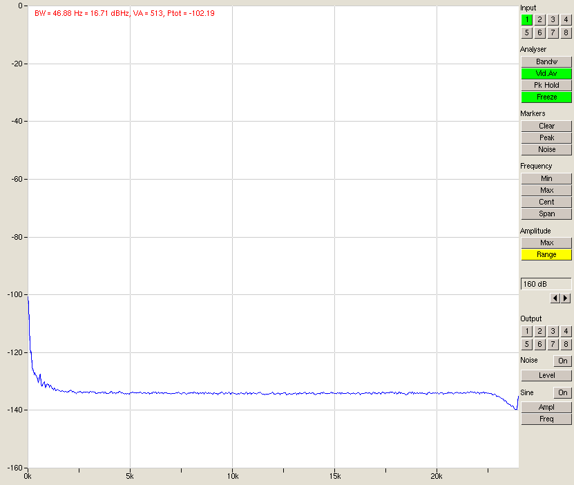
Fig. 2 – M-audio delta 1010 input shorted, -10 dBu setting
So clearly the noise is worse for the -10 dBu setting. If this sounds a bit contradictory, remember that if the D/A converter is fed a lower level signal for the same 0dBFS output, it will apply more gain to the signal, thus raising the noise relative to the signal.
By the way – soapbox time: Do not get tricked into thinking the noise floor is -135 dB here; that is not true. In fact, doing the FFT with more points would drop the apparent noise floor because what you’re really looking at is the noise times unit bandwidth. The bandwidth per measurement here is 46.88Hz (48000/1024) and the value of -135 dB is the power of all the noise integrated over that 46.88 Hz bandwidth. So if you drop the integration bandwidth (more FFT points), the noise integral also drops leading you to think you have a lower noise floor. But when you then add up the noise of these smaller but more plentiful FFT bins, you end up with the same total number. In the end, the value is relatively meaningless. The noise at any given frequency is zero per definition as the noise spectral density stays the same regardless of bandwidth. Rant over.
A bit of a problem occurs when Baudline is asked to do the same measurement:
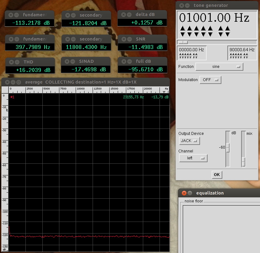
Fig. 3 – Baudline measuring a shorted input on the delta-1010 in +4dBu mode
It measures a noise level of -96 dB rather than the -107 Jaaa found and the noise distribution is suspiciously flat. I have to conclude for now that either I am making a measurement / configuration error or Baudline has a problem here (and not just because the Jaaa value is better or closer to the expectation).
D/A noise
This one is not directly measurable, because I have nothing than can measure this kind of performance…
- I do not have an analog power meter with a 1 uV accuracy
- measuring in the digital domain requires an A/D converter and as we just saw, its noise is higher than that of the DAC.
So, barring the use of a low-noise preamp, an audio precision or an accurate power meter, we will not know definitive figures. We can conclude though that the D/A noise is not going to be a dominant problem in the ultranalyzer. Some day I’ll find the motivation to drag the ultranalyzer to work and calibrate it against a SYS-2722.
Loopback noise and signal scaling
When we build a loopback connection (i.e. connecting the A/D input to the D/A output) we know now that the A/D noise should dominate. When we figure out how to best scale the signals we can proceed with distortion measurements. First, how does the noise propagate? This follows from the block diagram.

Fig. 5 – Loopback block diagram
We have as noise contributors roughly the D/A converter, the output stage G1, the input stage G2 and the A/D converter and the total noise follows as N(t) =
N(D/A)*G1*G2
+ N(G1) * G2
+N(G2)
+ N(A/D)
From this equation follows the classic engineering paradigm to put all the gain up front as the downstream gains appear multiple times in the equation, making everything much worse. So even though we want both G1 and G2 to be as low as possible, when we are faced with the boundary condition
G1 * G2 = 1
(for proper signal scaling) then we choose G1 to be large and G2 to be small: +4dBu settings for both output and input, as confirmed by our measurements above. In this way G1 is 25x (14 dB) larger than G2 and G2 (the input stage) is not amplifying the noise of G1 (the output stage) more than necessary. Going back to the equation, what we then expect to see is the sum of the noise of the A/D and the D/A converter, plus a contribution from the opamps. If those are well designed, then the loopback should perform only slightly worse than the A/D converter alone. Neglecting the opamp contribution, we expect -117 dB * G1*G2 + -107 dB, which when G1*G2=1 comes to -106.6 dB. And what do we see:
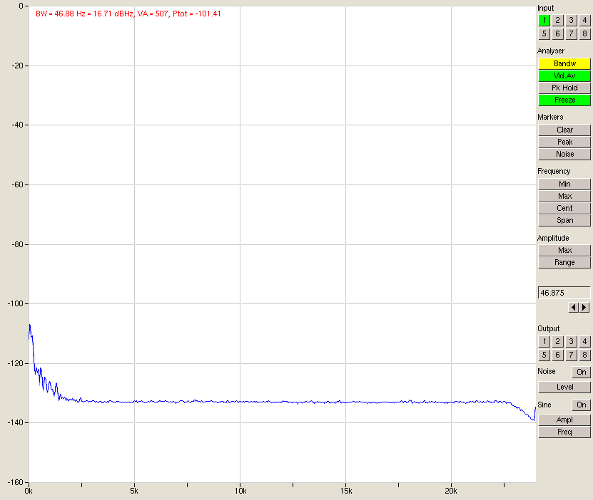
Fig. 4 – Loopback test on an M-audio delta 1010 @ 48 kHz. Both D/A and A/D are set to +4 dBu.
We get a noise level of -101 dB which is clearly worse than the A/D converter by itself. Immediately you would think to blame the D/A converter. Maybe it’s not achieving its -117dB? If we forget proper signal scaling for a moment and set the D/A to -10dBu, effectively setting G1*G2 to 1/25, the noise figure of the loopback doesn’t change at all. The D/A converter is not the culprit. When we set the A/D and D/A to -10dBu (keeping G1*G2 = 1) we get an SNR of 87 dB and 86 dB with A/D to -10 dBu, D/A to +4 dBu (the worst case). So back to the equation. The term that didn’t dominate is the D/A converter noise, even with G1*G2 of 25. The term N(G2) is constant so also can not be blamed. What remains is the term N(G1)*G2. This is examplified by changing G2 by a factor of 25 and watching the noise increase dramatically. Don’t blame G2 though: what is shows is that we are limited in this loopback configuration by the D/A converter output stage noise. Now this is interesting. What have we learned about using the ultranalyzer to analyse an analog system:
- Use +4 dBu for both A/D and D/A converters for minimal noise
- If we could find lower noise opamps for the D/A output stage, the performance could be up to 18 dB better.
Signal to noise ratio
Noise is not particularly interesting if a signal does not stand out from it. So not only the noise level is important but also the signal level.
Currently we can only measure SNR by measuring the signal power with no signal (= noise power), then applying the signal, measuring the signal power and subtracting the two in the dB realm, which is the ratio in the linear domain.
A potential problem is that the noise level can be modulated by the signal. That is why the better way (as applied by AP & co) will be to do both measurements on the same signal, i.e. measuring the signal power, and measuring the power of everything else. Jaaa cannot do this yet.
Dynamic range
The dynamic range is not much else except the SNR of the maximum signal the system will handle. We will therefore need to find the maximum allowable signal and determine the SNR under these circumstances to get an idea of the dynamic range of the system.
Especially in an un-calibrated system this is important since you may be amplifying or attenuating signals in order to fit your capture range. Under these circumstances it is essential to know what the maximum signal level can be and where the noise floor lies.
A question that may be raised is if the harmonics should be included into the calculation of the dynamic range. I do not do so – instead I split the undesired signals into noise, harmonic distortion and non-harmonic distortion (such as IMD).
Have we actually applied the maximum signal to the A/D by outputting 0dBFS from the D/A? We can check this by scaling the A/D converter down to -10 dBu and keeping the D/A converter at +4 dBu. Now we can overdrive the A/D converter by up to 14 dB and find the point where the sine wave starts to clip. If this point is higher than -14dBFS, that means there is additional headroom in the A/D converter.
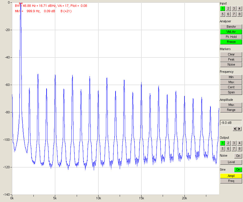
Fig. 5 – Clipping input at an output level of -9 dBFS
As expected, with full output scaled to +4dBu and an input scaled to -10 dBu we get clipping. Stepping down to -9 dBFS (Fig. 5) this doesn’t change.
-

Fig. 6 – Clipping disappeared and almost full 0dBFS output
But here we see the edge where clipping has vanished at an output of -9.3dBFS and a full-scale input on the A/D converter. So we seem to have some 5 dB of headroom in the A/D converter or to put it another way, the A/D converter has a maximum signal input of 0 dBFS.
Digital sourcery
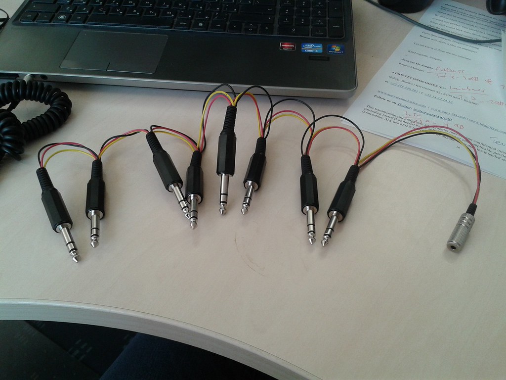
A contraption to cheat physics
So now we can measure signal level to determine dynamic range, we have the noise of our A/D converter and we know this noise is the system bottle neck. Or maybe not?
The delta 1010 has 8 A/D converter channels but when used as a digital signal analyser you are usually only interested in one channel. The other 7 are sitting by idly. That gave me an idea.
The noise in the system is the noise generated in the A/D converter and is uncorrelated between the channels, because each channel has its own front end. So if we were to sum up the A/D outputs the noise would scale up with the root of the sum of the squares, in other words for every doubling of the number of signals summed the noise would increase by 3 dB.
Why would we want that? Well, if we were to apply the same input signal to all A/D converters, the signal part of the sum of outputs would be correlated, and that means they sum up linearly, or by 6 dB for every doubling of the number of signals.
The signal to noise ratio then, would increase by 3 dB every time we double the number of signals. With 8 inputs, we can double the number of signals three times, potentially giving us 9 dB of increase in SNR! Now that is worth a try. Get soldering!

That’s how you wire channels in parallel in the analogue world…
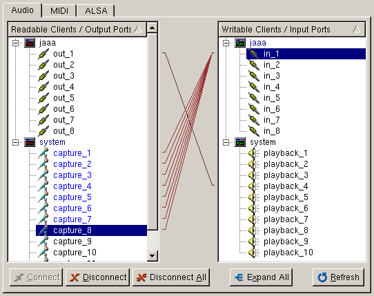
- …and that’s how you wire them together in the digital world.
As seen above, when you wire the inputs all to the same sink, jack simply adds up the signals. Since jack does floating point processing, you are able to add up multiple 0 dBFS signals and the output will not clip.
Now, drumroll… the results:
1 input in parallel
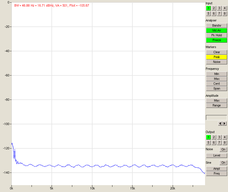
Fig. 7 – Noise, 1 input parallel
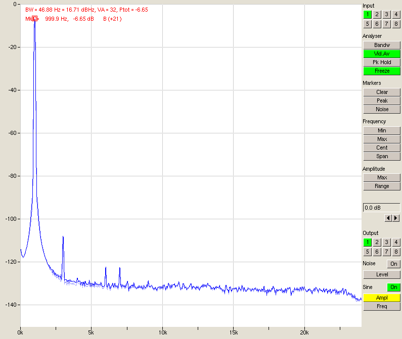
Fig. 8 – Signal, 1 input in parallel
2 inputs in parallel
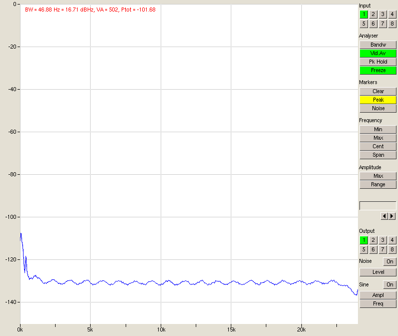
- Fig. 9 – Noise, 2 inputs in parallel

Fig . 10 – Signal, 2 inputs in parallel
4 inputs in parallel
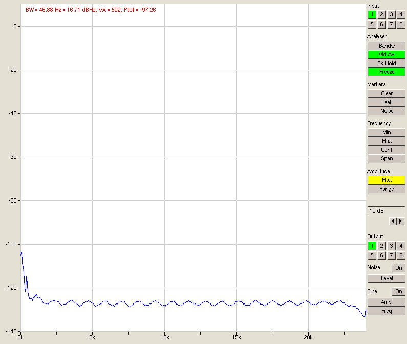
Fig. 11 – Noise, 4 inputs in parallel
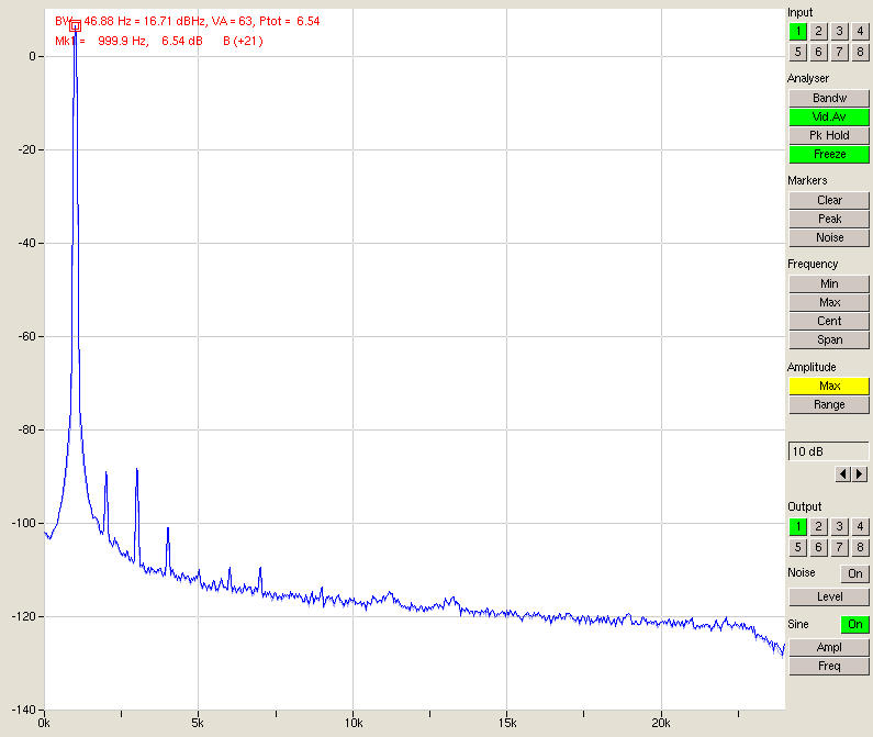
Fig. 12 – Signal, 4 inputs in parallel
8 inputs in parallel
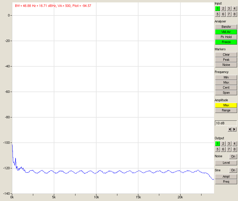
Fig. 13 – Noise, 8 inputs in parallel
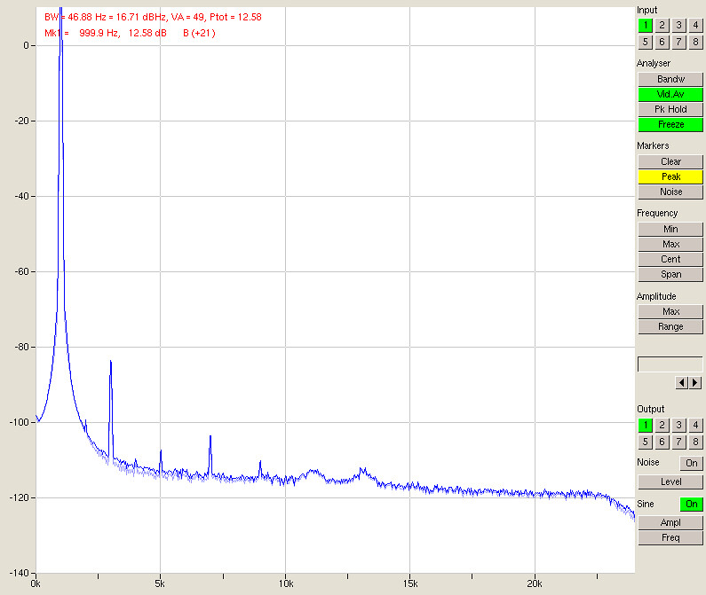
Fig. 14 – Signal, 8 inputs in parallel
|
1 in parallel |
2 in parallel |
4 in parallel |
8 in parallel |
|
| Signal power |
-6.6 dBFS |
-0.7 dBFS |
+6.5 dBFS |
+12.6 dBFS |
| Noise power |
-106.0 dBFS |
-101.7 dBFS |
-97.2 dBFS |
-94.6 dBFS |
| SNR |
99.4 dB |
101.0 dB |
103.7 dB |
107.0 dB |
Looking at the table above, we have a very clear improvement in SNR quite close to the predicted 3 dB per doubling. The differences are due to things other than noise (for instance, channel 1 has worse performance since it’s sitting directly next to the PSU and is picking up some hum) and at some point the noise from outside the A/D converters (e.g. the D/A or its output stage) will start to come into play.
Of course this concept is not very different from averaging: taking multiple measurements of uncorrelated noise and correlated signal in order to improve the signal-to-noise ratio. This method however does not depend on the signal staying constant over time.
If you bear in mind that a sine wave output at 0 dBFS is measured at -6 dBFS input (fig. 8), it becomes clear that the dynamic range can be as big as 107 +6 = 113 dB unweighted. Add A-weighting and we are very close to 120 dB. Using this little trick we have made the A/D converter about as good as the D/A, even if it is now quite a bit bigger.
THD+N
As is already obvious from some high-level plots, the harmonics will dominate the noise power so in order to verify the claim of the THD+N we can simply measure THD.
For the D/A converter the distortion is quoted at 0.002% or -94 dB. The A/D converter should do 0.00072% or -103 dB. In this case it’s the D/A that dominates so again we should see big differences when playing with the gain settings. However…
|
D/A -10 dBu |
D/A +4 dBu |
|
| A/D -10 dBu |
-98 dB |
-100.8 dB (*) |
| A/D +4 dBu |
-101.6 dB |
-99.0 dB |
| (*) (-9.4 dBFS D/A to prevent clipping) | ||
The 94 dB is exceeded by far. I measure somewhere between 98 and 102 dB. Both the cases when A/D and D/A have the same setting yield the highest THD, and that’s because the A/D and D/A sum up here. Indeed the difference is 2 to 3 dB, so we have to conclude that A/D and D/A are well matched.
There was a bit of a spanner in the works though. The trouble seems to be the switches and the jack plugs. On older units they need a good cleaning as corrosion can make for some quite crappy connections. Especially when you have multiple inputs in parallel each and every switch can throw a spanner in the works: a thorough cleaning will certainly not hurt, yet still it might be advisable to bypass them entirely, soldering the in/outputs hardwired to the board.
Further characterisation measurements
IMD seems to be at the level of THD. That’s nice.
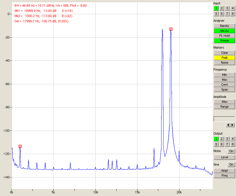
Fig. 15 – Full-scale IMD
A full-scale 20 Hz – 20 kHz frequency sweep (generated in Audacity) and a peak-hold measurement show frequency response flatness.
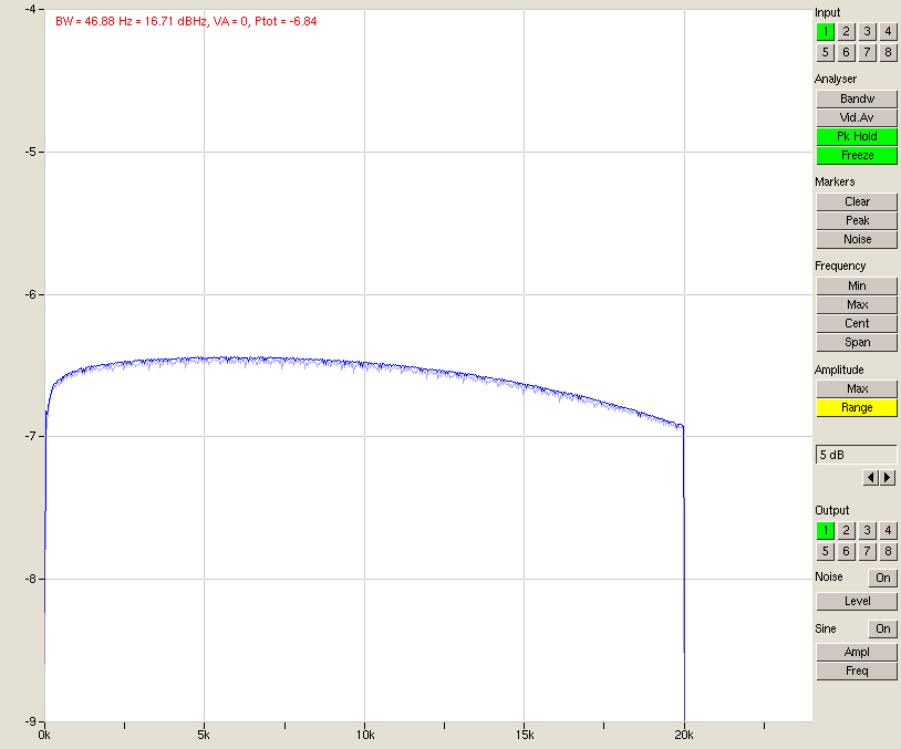
Fig. 16 – Frequency response
As may be seen above, the flatness of the curve is within +/-0.25 dB which again is exemplary for a complete loopback consisting of D/A, output- and inputstage, and A/D converter.
Good to see you back. I’ve admired your esl direct drive amp for a long time, been meaning to build it for my ML Requests. ( bigger version of SL3)
Mick
Hi Mick, nice to hear from you and thanks for the kind words. I’ll be sure to put your blog in my RSS feeds. I reckon you’ll want to stay tuned to see the ideas I have up my sleeve for computer based audio 🙂