last update: August 20, 2003

[ schematic (pdf, 4 kB) ]
Also, the cathodes which are heating up will experience an unusual high pull on their yet weak emission. This can cause the barium on the cathode to simply be blown off the cathode and is called cathode poisoning or cathode stripping. Obviously this will shorten the tube life. If all of this isn't enough, an RC-loaded tube stage will see the full B+ on the tubes' anodes until the tubes start passing current and dropping voltage over the load resistor. Enough reasons all in all to wait a while and provide a soft-start to your amps to save tube and other components' life, and make the circuit saver.
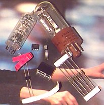
If you check out old measuring equipment such as Tektronix and HP tube oscilloscopes, you will find that they all incorporate HV delay relays. These are tubes with bimetal contacts that close after about 60 to 80 seconds. Now these are cool tubes, but quite scarce. Besides, they're not in the signal path, so why bother with expensive stuff.
Here's a little circuit that does the same thing as those HV delay relay tubes, for less than a buck.

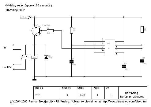
According to the datasheet, the on-time of this one-shot is 1.1 * R3 * C2 in seconds, but in practice half of that is enough, so if C2=1200 uF, R3=33 kohm that yields about 1 minute of delay.
R1 and C1 generate a less-than-two-thirds-of-vcc trigger pulse to start the 555, so something like R1=1k, C1=100uF will do nicely. The additional advantage is that when the supply is interrupted for a short while (i.e. seconds) the output goes high immediately when power is restored, which is what you'd like to see, since your filaments aren't cold yet. After being off for several minutes C1 is empty, which means a new trigger pulse is generated when switched back on.
The output (pin 3 on the 555) is inverted by the PNP, which drives the AC relay. The relay is protected from reactive primary coil surges by the diode.
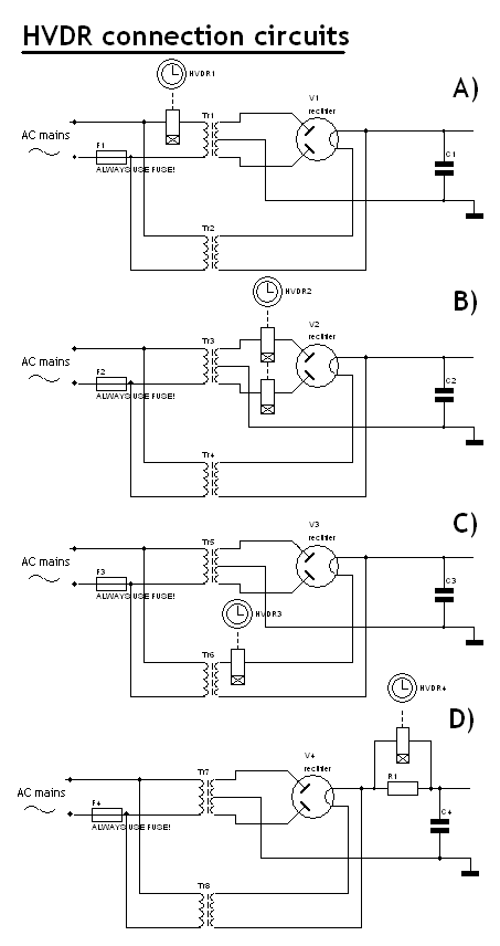
As to the connection of the high voltage, there basically are 4 options:

- Connection A switches the HV transformer on its primary winding. This is quite safe and you can use a normal relay. However, if the same transformer also provides a secondary winding for other parts of the circuit which need power right away (for instance the heaters of the tubes you wanted to pre-glow in the first place), you can't use it and need to resort to another connection diagram.
- Connection B switches the HV transformer on its secondary winding. Be careful in selecting the relay: many relays are not suited for more than 250 VAC and it's not recommended to exceed this rating.
- Connection C switches on the rectifier filament winding. This has the advantage of switching a low voltage (relays are usually pretty highly rated on current, no worries there) and as the rectifier starts conducting gradually, the HV comes on softly. The soft start reduces the inrush current into the capacitors. Take in mind that the isolation between relay coil and switch is high enough, so that the HVDR is not damaged by the B+, which is the potential the switch will be at.
- Connection D is a variation of connection B with a soft start. It allows a mere low current through the resistor to slowly charge the capacitors in the power supply. After that, the relay will short the resistor so that the rectifier can deliver real power. At the moment of the start, there's still a high voltage across the relay contacts, so again mind the voltage rating on the relay. Also, mind the wattage rating of the inrush limiting resistor. Safety first!
On the top left corner the DC supply of 5 to 15 volts is connected. The 'enable' jumper allows you to include a
low-voltage start or power
switch or have the HVDR switched on by another HVDR (daisy chaining).
In the latter case, you can chain your entire system
from source to poweramps, thus ensuring the system starts up in the right sequence (sources first, preamps and poweramps
after that). If not used, the enable jumper must be shorted.
Copper side, 600 dpi, 100%, 1 PCB
Copper side, 600 dpi, 100%, 8 PCBs