class A discrete transistor output stage for Sony DVP-NS900V
last update: May 21, 2003

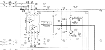
The above circuit is repeated for all channels, including the stereo outputs. It is absolute textbook material. A gain of 1.2 provides for an exact 2V rms output (=5.6 Vpp) when driven from the 2.5 Vppdiff the DAC outputs.
AK4357 datasheet (286 kB pdf)
AK4383 datasheet (282 kB pdf)
So, if it is textbook material, why replace it? Well, because engineering is about tradeoffs. And I did not like the point where the tradeoff lies in this design. The opamp impresses with low distortion and low power dissipation, which to a certain extent compromises audio quality. The losses lie in crossover distortion and intermodulation due to its class-B design. The reason why you don't see this in the measured distortion (on 1kHz sine waves) is because of the high amount of global feedback.
However, since I don't listen to 1 kHz sine waves all day, we need to look a little further. An opamp relies on two basic
priciples: high loop gain and 1st order behavior. This is accomplished by a dominant pole, which is usually at around 10 Hz.
This 1st order behavior however implies that as frequency rises, the loop gain of a feedback system is declining and nonlinearities
become more evident. It is this attribute that is very important in digital systems and especially 1 bit systems. These
employ noise shaping to make up for their poor quantization. In effect, most of the signal energy is located above the audio
band.
Suppose an opamp with a GBW of 10e6 (which is a realistic value). Its loopgain is a mere 40 dB at 100 kHz. In 1 bit systems,
this is where the increase in noise begins!. Suffice it to say that the opamp can not be used to filter out the 1-bit
quantization remains. Sony uses one order around the opamp which will do a little, and does the rest in a passive filter
before the opamp inputs.
Another opamp limitation lies in the slew rate. While it will amplify signals of 10 MHz, it will do so to only a very small amplitude, and the slewrate is the limiting factor. Because slewrate is the slope of the signal, it increases with frequency (this follows from basic calculus). Once the slewrate is exceeded, the opamp will create vast amounts of harmonics (take a look at a triangle wave spectrum). These signal dependent harmonics, along with associated IM products, are very hard to predict and measure for an arbitrary stochastic signal (such as music), but easy to hear.
The opamp itself is a tad redundant. Its virtues: high Zin, low Zout are both wasted: Zin is set to 4k2 by the resistor configuration and Zout is set to 1 kOhm by the mute protection resistors. The gain of 1 will be maintained to around 10 MHz, but one really doesn't need 40 transistors and 120 dB of gain to accomplish this. Time for a revision.

Well, this is textbook as well, but another chapter.
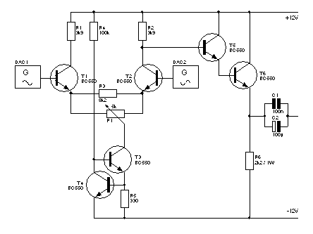
This stage connects to the holes left behind when the opamp was removed. The resistors R123/R126 from the non-inverting
inputs to ground were removed to prevent a 6 dB level difference between the two balanced dac outputs since there is no more
global feedback.
For a gain of 1 and a low output impedance, all you need is an emitter follower. However, to maintain the 2V rms output level and the obligatory factor 1.2 some gain is required. This is what the differential stage is for. The pot in the emitterconnection allows for careful distortion cancellation (that is, if you have a distortion analyzer, he he ;-). The DAC has 2.5VDC on its outputs. Collectorcurrents are 1 mA, thus the 5.6Vpp will not run into clipping problems.
The constant current source speaks for itself I presume. The inverted output of the inverting input (read that twice...) is fed to the emitter follower which is running at 10 mA class A bias so that it will maintain a low output impedance for the entire signal without running into class B (fatal in single ended designs!). Note that you may just as easy make a differential output by adding another emitter follower (I will add this to the 2ch outputs since my preamp is differential). The output transistor has an input impedance (Hfe/gm) of about 750 Ohms. Since this is in the same order of magnitude as the collector resistor, a darlington configuration was implemented to boost the 7k5 to about 225 kOhm.
The output of the emitter follower is passed through a coupling cap (maybe I'll implement a servo soon) and directly fed to the outputs, bypassing the mute transistors and accompanying output resistors. Of course you can also route the outputs in the intended way if you do not want to modify too much or are afraid of turn-on bumps.
 Connected thus the player started sounding really nice, with a solid bass reproduction and very good spatial coherence.
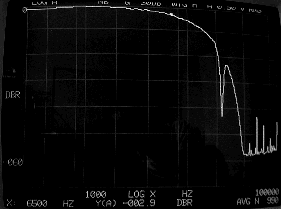
However, overall sound was still a little soft, much like a tube amp ironically. Time for the mighty spectrum analyzer. Ouchie!
A bandwidth of 6.5 kHz, dull sound indeed.
After some pondering the cause struck me. The filtering caps C101/C102 and C109/C115 were calculated by Sony with the 2k4 feedback resistor in mind. My situation is different, I can allow for it because the 2k4 loading resistors are removed. The caps were replaced with 180 and 270 pF silvered micas respectively. Also I removed C106/C118 and C112/C121, since the base-collector miller capacitance of the diffential input stage transistors are in the same ballpark. Thus a 3rd order 50 kHz characteristic is once again obtained.
 Now, in the next measuring round things started to look a lot better. All of the HF resonances are gone and you can clearly
see the onset of analog filtering at 50 kHz. However, I still found a 16.5 kHz pole. That was weird.
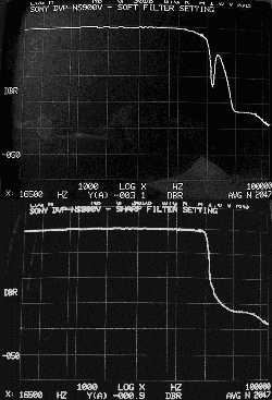
After an hour of thinking and searching for parasitic capacitances I shouted something that can not be repeated here when I remembered that the 900V has two digital filter settings: soft and sharp rolloff. I had played around with both and ended up with a (slight) preference for the soft roll-of type. As is visible from the plots to the right, this filter allows a relatively large amount of alias remains to pass through (everything after the 22 kHz notch).
After connecting a TV set (aargh) and resetting the filter to sharp rolloff mode I got a flat response. Phew! The measuring gear made itself very useful once again, my ears had provided the right direction but I would have never got this result without proper tools.
Allright, time to drag the machine back into the living room, fire up the rig and see what the result sounds like.
And then something snapped. This simple, 6 transistor, global feedback free class A stage has totally transformed this player.
I can now much more clearly hear the differences between the filter settings and oddly enough, I now absolutely prefer the
'sharp' setting. This is because the highs are in no way sharp or what is known as 'digital' sounding. They're fresh and open.
At the same time there is a bass definition and control that is unprecedented. Along with awesome depth it oozes fun.
